What is Optical Gas Imaging (OGI) or gas visualization?
Gas visualization or Optical Gas Imaging (OGI) is the science of imaging gases. There are several techniques for visualizing a gas, but in this article we will cover gas visualization using thermal cameras.
Why can we visualize certain gases in infrared?
Thermal imaging cameras measure heat energy. Due to the rotation and vibration of molecules, certain gases can absorb electromagnetic energy. The energy that can be absorbed (recorded) can also be emitted (radiated).
Gases consisting of 1 atom (e.g. Helium - He -, Neon - Ne - or Krypton - Kr -) and gases consisting of 2 atoms (e.g. Hydrogen gas - H -, Oxygen - O - or Nitrogen - N -) do not create these vibrations. More complex gases such as Methane (CH4), Carbon dioxide (CO2) or Sulfur Hexafluoride (SF6) are just some of the examples that can absorb electromagnetic energy.
So with a gas detection camera, you want to distinguish between the energy absorbed/emitted by the gas itself and the amount of energy coming from the environment.
What is needed to visualize the gas?
A gas detection camera is built with a sensor or spectral filter that is highly sensitive to the spectral band in which the gas absorbs IR light.
Schematic representation absorption of gas.
Can any thermal imaging camera see gases?
Thus, to visualize a gas, there must be a difference in the emitted amount of energy of the gas and its environment or background. In practice, the amount of energy reflected from the gas is negligible. In other words, the greater the difference in radiation between the gas and its surroundings the better the gas can be observed with the gas detection camera.
To visualize a gas with a thermal imaging camera, it is important that the gas absorb light in the spectral band in which the camera is built. Most portable, uncooled thermal imaging cameras measure in a range of 7.5-14µm.
It is necessary for the thermal imaging camera to be able to detect a radiation difference between the gas and the environment on the one hand. Most gases are not visible with a standard thermal camera.
Water vapor, the gas phase of water, is not visible in the air by the human eye. As humans, we see the condensation of the gas in the air when the water vapor comes into contact with an air temperature below the dew point. Since that water is opaque (not transparent) to a thermal imaging camera, we can observe this water vapor better with a thermal camera than with our naked eye.
If a gas has a high transparency of light in the spectral range of the camera, the thermal camera will not be able to detect the gas. These transparency curves as well as the spectral bands of thermal imaging cameras can be accessed online. Thermal Focus can help you with this.
NH3 gas leak identified with FLIR G306.
Refrigerated versus uncooled gas detection cameras
FLIR Gx320 - VOC gas detection camera
FLIR GF77 - uncooled gas detection camera
Gas detection cameras are among the most sensitive thermal imaging cameras on the market. To measure in certain wavelengths at low temperatures, it is necessary to use a sensor that is sensitive in that spectral range.
A distinction can be made between Refrigerated gas detection cameras and uncooled gas detection cameras. When talking about refrigerated gas detection cameras, we refer to an infrared camera with a sensor operating at cryogenic temperatures. The sensors are cooled to about 70K or -203°C. The most commonly used sensors for the 3-5µm range are the InSb (antimonide) detectors and for the 8-12µm wavelength the QWIP (quantum well infrared photodetector). To cool these sensors, a micro stirling cooler is usually used.
FLIR micro stirling cooler
Uncooled gas detection cameras operate with a detector that does not require deliberate cooling. This type of cameras is also used only in LWIR to visualize gases.
The choice between a cooled and uncooled thermal imaging camera is determined by 2 factors:
The most important factor is the wavelength in which the camera operates. This wavelength must correspond to the spectral band in which the gas can absorb electromagnetic energy.
The price/quality ratio
Uncooled sensors are generally cheaper to produce, but have the disadvantage of being able to convert much less infrared light to an image, so sensitivity is drastically lower than with cooled thermal imagers. Because they operate in LWIR (8-12µm), the gases visible in the MWIR (3-5µm) portion of the infrared spectrum can already not be detected at all. The sensitivity of the cooled and uncooled thermal imaging cameras is hardly comparable. Here, the cooled thermal imaging cameras provide superior image quality and sensitivity compared to the uncooled cameras because they suffer less from electronic noise due to cryogenic cooling.
Spectral filtering to visualize gases
A sensor is built to see well through the air with limited influence of gases present in the air such as CO2, H2O, CH4 and O3. These gases reduce the transmission of infrared light through the air. This is the reason why thermal imaging cameras are mainly built in MWIR (3-5µm) and LWIR (8-12µm) and there is little interest in the zone between 5-8µm, for example.
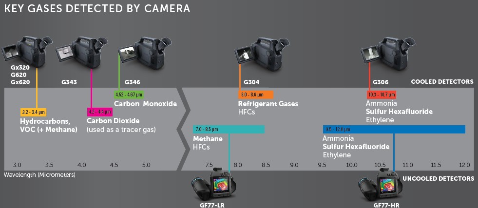
Presentation of the main detectable gases by gas visualization camera in the infrared spectrum.
Although a sensor is sensitive in a wider infrared spectrum, a spectral filter is used. The FLIR Gx320 is a gas detection camera that has an InSb detector (3-5µm), but has a filter that passes through the spectral band of 3.2-3.4µm. As many as 400 different gases are visible in this spectral band. This is why we also call the FLIR Gx320 the VOC camera. VOC stands for volatile organic compounds.
Gases that can thus absorb the infrared light in the spectrum where the gas detection camera is imaging this part of the spectrum thus become visible.
Spectral band of Ethylene compared to the range of the FLIR G306.
Spectral band of propane compared to the range of the FLIR Gx320 and the FLIR G620.
A brief overview of visible gases in IR
Schematic representation of the main detectable gases by gas detection camera.
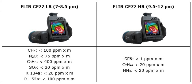
Schematic representation of the main, detectable gases of the FLIR GF77 OGI camera.
What does a gas leak look like?
To visualize a gas, an advanced frame substraction filter is used. In thermal cameras, you can find this as a high sensitivity mode (HSM). The filter aims to start comparing images with each other over a time span. There is interest in a radiation difference that can be observed by the camera. The delta radiation of each pixel is displayed in a smooth manner. Since the gas is in motion, a delta radiation is created due to the concentration differences of the gas.
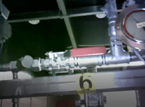
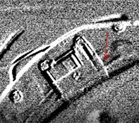
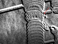
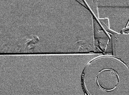
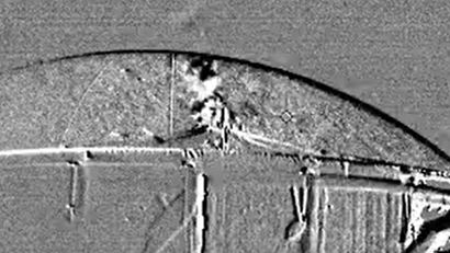
This produces images like the ones below:
Figure 9: CO2 leakage detected with FLIR GF343Figure 10: SF6 leaks detected with GF306Figure 11: NH3 Leak detected with FLIR GF306Figure 12: CO leak detected with GF346Figure 13: CH4 Leak detected on biogas plant with FLIR GFx320